Physically Based Rendering Algorithms: A Comprehensive Study In Unity3D - Part 1 - Introduction

.png?ixlib=gatsbyFP&auto=compress%2Cformat&fit=max&w=2048&h=2048)


Physically-Based Rendering (PBR) has become the industry standard for defining materials within games, animations, and VFX. Unity, Unreal, Frostbite, ThreeJS, and many more engines provide their own implementations of PBR, democratizing access to high fidelity graphics for a variety of studios. In the last 10 years, we've seen a massive shift in rendering pipelines. Realtime rendering, made easy by Unreal and Unity, has enabled even the smallest studios and teams to produce content on a level that used to take legions of artists to produce. Today, it is hard to find artists that are not familiar with the pipeline, but it can still be hard to find engineers and technical artists who are familiar with how the pipeline actually works behind the scenes. I created this study to break down Physically Based Rendering and make it as easy to understand as possible, whether you are a beginner or an expert. However, to follow along here, I am going to assume that you already understand the concept of a material and that materials are typically defined using a "shader". What we are covering in this article is different PBR algorithms, and how shaders / materials can deploy those algorithms, specifically within Unity3D. There are a lot of moving pieces, but I'll do my best to simplify the concepts and provide you with resources to build your own Physically Based shading models, or improve your understanding of the mechanics under the hood of engines like Unity and Unreal.
What is the "Physicial" in Physically Based Rendering?
To really understand PBR, you first need to understand some basic theory around how lighting works in games.
When you view a scene or object in three dimensional space, you are viewing it through a two dimensional context. To pull this off, rendering engines rely on a lot of magic under the hood. What matters most in this magic is how those rendering pipelines calculate lighting & surfaces in 3D space. Of course, that data will eventually be transformed so that it can be represented as a single pixel on your screen, but we aren't going to focus on that part of the process for this exercise.
What we will focus on is how light interacts in three dimensions, and how we try to represent those interactions in a manner that can eventually be captured and displayed in two dimensions.
What follows here is a dramatic oversimplification that only serves to help you understand some core concepts in rendering theory.
1. Think of light as being a laser beam.
That laser beam has an origin and a direction in which the light is traveling. This is commonly called the "light direction", and usually represents a complicated formula that includes the intensity ("power", "strength", etc) of the light, its falloff ("reduction", "attenuation", etc) over a certain distance, and the color of the light. Depending on what rendering pipeline you are using, and what engine you are using, there are numerous means and methods relied on to calculate and serve lighting information to shaders. The light itself, is really the most complicated portion in 3D rendering. PBR is complex because of how we use that lighting information. Bad lighting information = bad PBR. Really it just means bad rendering, since it can't be physically based without good light data.
2. Think of every point along a surface actually just being a direction in 3d space.
That direction, commonly referred to as a "normal", is used to calculate the angle of a surface in three dimensions. This is a really important concept to grasp, as it is a core component of Physically Based Rendering. If you have ever created "normal maps", you have effectively created an instruction sheet for a render pipeline to represent the detail of a surface in leu of actual geometry.
3. Think of your eyes as also shooting laser beams.
This viewpoint, commonly referred to as "view direction", is usually a representation of a camera and the direction it is pointing.
It all comes together
To understand PBR, you have to understand the above concepts and how they interact with each other in three dimensions. Light bounces all over the place in a scene. Surfaces point in all sorts of different directions. You could be positioned anywhere in that scene, and looking at any direction. What you actually see when you look is how light is behaving with surfaces, before that light shoots into your eyeballs. Again, dramatic oversimplification. Most rendering engines actually rely on concepts like forward rendering, deferred rendering, ray-tracing, path-tracing, radiosity, and sampling rather than real world ocular light absorption.
So what is Physicially Based again?
The term physically based really just indicates that we are using physical mathematical models to approximate the above behaviors. In this exercise we are relying on a specific function, known as the Bidirectional Reflectance Distribution Function (BRDF), to calculate our Physicially Based rendering. What makes the BRDF physical is really having 3 properties:
- positivity (the output of the model is always positive)
- reciprocity (switching the source of light and the view point will not change the output. Think if I can see you, you can see me)
- energy conservation (an object can not reflect more light (energy) than it receives)
If the above 3 properties are true, then the BRDF is physically based. Boom goes the dynamite, and that is what sort of algorithms we will be looking at.
I've talked a lot about light. The real core of PBR isn't the light itself, it is the surface! The surface of an object determines the behavior of light. What BRDFs try and accomplish is the calculation of light behavior on the surface! The rest of this article will be focused on that.
Surfaces, surfaces, surfaces
In order to understand how light and your viewpoint interact with surfaces (normals) you have to first understand surfaces (normals) themselves. When light shines on a perfectly smooth surface, it will reflect off that surface in an almost perfect way. When light interacts with what we call a rough surface, it will not be reflected perfectly. This is the core of PBR, BRDFs, and Energy Conservation. The reflective nature of surfaces, or lack thereof, can be explained by the existence of something called a microfacet. Every surface is made up of microfacets. When you define the roughness of a surface, you are defining the prevalence and intensity of microfacets!


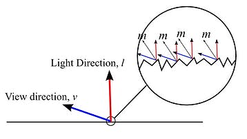
When you look at an object, the first safe assumption you can make is that its surface is not perfectly smooth and is actually composed of many very tiny facets. Each of these facets is a potentially imperfect specular reflector. These tiny imperfections have normals that must be distributed across the surface. The degree to which microfacet normals differ from the surface normal is determined by the roughness of the surface. This distribution is the core component to managing the roughness of a surface. The more rough the surface, the more potential exists for disruption to the specular highlight. Because of this, rougher surfaces have larger and dimmer looking specular highlights. Smooth surfaces can cause the specular highlight to compress as the light is reflected more perfectly than before.


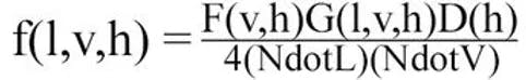
Now back to the BRDF. BRDF algorithms feature a more complicated shading model than other algorithms. This shading model is technically 3 pieces of a single whole: the Normal Distribution Function, the Geometric Shadowing Function, and the Fresnel Function. Together they make this algorithm, which we will break down later:
To really understand a BRDF, you need to understand the 3 functions that make up a BRDF. You can use any combination of these three functions to build your BRDF. Caveat, it really depends on what you are trying to accomplish. At the end of the day, a Lambert shader is still physically based. It just represents a perfectly diffuse surface by a constant BRDF (NdotL!). Let's hit each of these in turn to make a shading model that will work for us.
Writing a PBR Shader: Nuts, Bolts, and Smooth Surfaces
What are the Properties of a PBR Shader?
In most PBR shading models, it is quite usual to see a few of the same properties influencing them in some format. The two most important properties in modern PBR approaches are Smoothness (or Roughness) and Metallic. Both of these values work best if they are between 0..1. There are many different approaches to building PBR shaders, and some of them allow for using the BRDF model for more effects, such as Disney's PBR Pipeline, each effect being driven by a specific property.
Let's move to building our properties out, if you haven't checked out my page on Writing Shaders in Unity now would be a great time to head over and read that.
Shader "Physically-Based-Lighting" {
    Properties {
    _Color ("Main Color", Color) = (1,1,1,1)                    //diffuse Color
    _SpecularColor ("Specular Color", Color) = (1,1,1,1)        //Specular Color (Not Used)
    _Glossiness("Smoothness",Range(0,1)) = 1                    //My Smoothness
    _Metallic("Metalness",Range(0,1)) = 0                    //My Metal Value

    }
    SubShader {
	Tags {
            "RenderType"="Opaque"  "Queue"="Geometry"
        }
        Pass {
            Name "FORWARD"
            Tags {
                "LightMode"="ForwardBase"
            }
            CGPROGRAM
            #pragma vertex vert
            #pragma fragment frag
            #define UNITY_PASS_FORWARDBASE
            #include "UnityCG.cginc"
            #include "AutoLight.cginc"
            #include "Lighting.cginc"
            #pragma multi_compile_fwdbase_fullshadows
            #pragma target 3.0

float4 _Color;
float4 _SpecularColor;
float _Glossiness;
float _Metallic;
So here we have defined our public variables in our Unity Shader. We will add more later, but this is a good start. Below the properties is the initialization structure of our shader. We will refer to the #pragma directives later on as we continue to add more functionality.
Vertex Program
Our Vertex Program is extremely similar to the one produced in the tutorial for Writing Shaders in Unity. The key elements we need are the normal, tangent, and bitangent information about the vertex, so we make sure to include those in our Vertex Program:
struct VertexInput {
    float4 vertex : POSITION;       //local vertex position
    float3 normal : NORMAL;         //normal direction
    float4 tangent : TANGENT;       //tangent direction
    float2 texcoord0 : TEXCOORD0;   //uv coordinates
    float2 texcoord1 : TEXCOORD1;   //lightmap uv coordinates
};

struct VertexOutput {
    float4 pos : SV_POSITION;              //screen clip space position and depth
    float2 uv0 : TEXCOORD0;                //uv coordinates
    float2 uv1 : TEXCOORD1;                //lightmap uv coordinates

//below we create our own variables with the texcoord semantic.
    float3 normalDir : TEXCOORD3;          //normal direction
    float3 posWorld : TEXCOORD4;          //normal direction
    float3 tangentDir : TEXCOORD5;
    float3 bitangentDir : TEXCOORD6;
    LIGHTING_COORDS(7,8)                   //this initializes the unity lighting and shadow
    UNITY_FOG_COORDS(9)                    //this initializes the unity fog
};

VertexOutput vert (VertexInput v) {
     VertexOutput o = (VertexOutput)0;
     o.uv0 = v.texcoord0;
     o.uv1 = v.texcoord1;
     o.normalDir = UnityObjectToWorldNormal(v.normal);
     o.tangentDir = normalize( mul( _Object2World, float4( v.tangent.xyz, 0.0 ) ).xyz );
     o.bitangentDir = normalize(cross(o.normalDir, o.tangentDir) * v.tangent.w);
     o.pos = mul(UNITY_MATRIX_MVP, v.vertex);
     o.posWorld = mul(_Object2World, v.vertex);
     UNITY_TRANSFER_FOG(o,o.pos);
     TRANSFER_VERTEX_TO_FRAGMENT(o)
     return o;
}
Fragment Program
In our fragment program, we will want to define a set of variables that we can use in our algorithms later:
float4 frag(VertexOutput i) : COLOR {

//normal direction calculations
     float3 normalDirection = normalize(i.normalDir);

     float3 lightDirection = normalize(lerp(_WorldSpaceLightPos0.xyz, _WorldSpaceLightPos0.xyz
 - i.posWorld.xyz,_WorldSpaceLightPos0.w));

     float3 lightReflectDirection = reflect( -lightDirection, normalDirection );

     float3 viewDirection = normalize(_WorldSpaceCameraPos.xyz - i.posWorld.xyz);

     float3 viewReflectDirection = normalize(reflect( -viewDirection, normalDirection ));

     float3 halfDirection = normalize(viewDirection+lightDirection);

     float NdotL = max(0.0, dot( normalDirection, lightDirection ));

     float NdotH =  max(0.0,dot( normalDirection, halfDirection));

     float NdotV =  max(0.0,dot( normalDirection, viewDirection));

     float VdotH = max(0.0,dot( viewDirection, halfDirection));

     float LdotH =  max(0.0,dot(lightDirection, halfDirection));

     float LdotV = max(0.0,dot(lightDirection, viewDirection));

     float RdotV = max(0.0, dot( lightReflectDirection, viewDirection ));

     float attenuation = LIGHT_ATTENUATION(i);

     float3 attenColor = attenuation * _LightColor0.rgb;
Above are the variables we will build with the data that Unity gives us, per the description in the Unity Shader Tutorial. These variables will be used repeatedly throughout our shader as we move to build the BRDF.
Roughness
In my approach, I remap roughness. The reason I do this is more of a personal preference, as I find that roughness remapped to the below produces much more physical results.
float roughness = 1- (_Glossiness * _Glossiness);   // 1 - smoothness*smoothness
roughness = roughness * roughness;
Metallic
Some more housekeeping. There are a lot of concerns when using Metallic in a PBR shader. You will find that none of the algorithms account for it, so we include it in a different format entirely.
Metalness is a control value to determine whether a material is a dielectric material (a non-metal, i.e. metalness = 0) or a metal (metalness = 1) material. Therefore, to have our Metallic value affect our shader in the right way, we are going to plug it into our diffuse color and have it drive our specular color. Since a metal will not show any diffuse reflection it will have a completely black diffuse albedo, while its actual specular color will change to reflect the surface of the object. See below:
The Guts of Our Shader
Below is the basic shader format that we will be building on. Please note the comments as they will help to organize and inform as to where we will be inserting our code.
Shader "Physically-Based-Lighting" {
    Properties {
    _Color ("Main Color", Color) = (1,1,1,1)                    //diffuse Color
    _SpecularColor ("Specular Color", Color) = (1,1,1,1)        //Specular Color (Not Used)
    _Glossiness("Smoothness",Range(0,1)) = 1                    //My Smoothness
    _Metallic("Metalness",Range(0,1)) = 0                    //My Metal Value


// future shader properties will go here!! Will be referred to as Shader Property Section
    }

    SubShader {
	Tags {
            "RenderType"="Opaque"  "Queue"="Geometry"
        }
        Pass {
            Name "FORWARD"
            Tags {
                "LightMode"="ForwardBase"
            }
            CGPROGRAM
            #pragma vertex vert
            #pragma fragment frag
            #define UNITY_PASS_FORWARDBASE
            #include "UnityCG.cginc"
            #include "AutoLight.cginc"
            #include "Lighting.cginc"
            #pragma multi_compile_fwdbase_fullshadows
            #pragma target 3.0

float4 _Color;
float4 _SpecularColor;
float _Glossiness;
float _Metallic;

//future public variables will go here! Public Variables Section

struct VertexInput {
    float4 vertex : POSITION;       //local vertex position
    float3 normal : NORMAL;         //normal direction
    float4 tangent : TANGENT;       //tangent direction
    float2 texcoord0 : TEXCOORD0;   //uv coordinates
    float2 texcoord1 : TEXCOORD1;   //lightmap uv coordinates
};

struct VertexOutput {
    float4 pos : SV_POSITION;              //screen clip space position and depth
    float2 uv0 : TEXCOORD0;                //uv coordinates
    float2 uv1 : TEXCOORD1;                //lightmap uv coordinates

//below we create our own variables with the texcoord semantic.
    float3 normalDir : TEXCOORD3;          //normal direction
    float3 posWorld : TEXCOORD4;          //normal direction
    float3 tangentDir : TEXCOORD5;
    float3 bitangentDir : TEXCOORD6;
    LIGHTING_COORDS(7,8)                   //this initializes the unity lighting and shadow
    UNITY_FOG_COORDS(9)                    //this initializes the unity fog
};

VertexOutput vert (VertexInput v) {
     VertexOutput o = (VertexOutput)0;
     o.uv0 = v.texcoord0;
     o.uv1 = v.texcoord1;
     o.normalDir = UnityObjectToWorldNormal(v.normal);
     o.tangentDir = normalize( mul( _Object2World, float4( v.tangent.xyz, 0.0 ) ).xyz );
     o.bitangentDir = normalize(cross(o.normalDir, o.tangentDir) * v.tangent.w);
     o.pos = mul(UNITY_MATRIX_MVP, v.vertex);
     o.posWorld = mul(_Object2World, v.vertex);
     UNITY_TRANSFER_FOG(o,o.pos);
     TRANSFER_VERTEX_TO_FRAGMENT(o)
     return o;
}

//helper functions will go here!!! Helper Function Section


//algorithms we build will be placed here!!! Algorithm Section


float4 frag(VertexOutput i) : COLOR {

//normal direction calculations
     float3 normalDirection = normalize(i.normalDir);

     float3 lightDirection = normalize(lerp(_WorldSpaceLightPos0.xyz, _WorldSpaceLightPos0.xyz - i.posWorld.xyz,_WorldSpaceLightPos0.w));

     float3 lightReflectDirection = reflect( -lightDirection, normalDirection );

     float3 viewDirection = normalize(_WorldSpaceCameraPos.xyz - i.posWorld.xyz);

     float3 viewReflectDirection = normalize(reflect( -viewDirection, normalDirection ));

     float3 halfDirection = normalize(viewDirection+lightDirection);

     float NdotL = max(0.0, dot( normalDirection, lightDirection ));

     float NdotH =  max(0.0,dot( normalDirection, halfDirection));

     float NdotV =  max(0.0,dot( normalDirection, viewDirection));

     float VdotH = max(0.0,dot( viewDirection, halfDirection));

     float LdotH =  max(0.0,dot(lightDirection, halfDirection));

     float LdotV = max(0.0,dot(lightDirection, viewDirection));

     float RdotV = max(0.0, dot( lightReflectDirection, viewDirection ));

     float attenuation = LIGHT_ATTENUATION(i);

     float3 attenColor = attenuation * _LightColor0.rgb;

     float roughness = 1- (_Glossiness * _Glossiness);   // 1 - smoothness*smoothness

     roughness = roughness * roughness;

     float3 diffuseColor = _Color.rgb * (1-_Metallic) ;

     float3 specColor = lerp(_SpecularColor.rgb, _Color.rgb, _Metallic * 0.5);

    //future code will go here!    Fragment Section

     return float4(1,1,1,1);
}
ENDCG
}
}
FallBack "Legacy Shaders/Diffuse"
}
The above code should create a white object when attached to a material in Unity. We will extend this shader by placing properties in the Properties Section, Variables in the Variables Section, Helper Functions in the Helper Function Section, Algorithms in the Algorithm Section and implementing the shader code in the Fragment Section.
You've got the barebones of a shader that we can extend to build whatever lighting models we want. In the next article we will go through the different Normal Distribution Functions, which define how microfacets normals distribute across a surface.
About Jordan Stevens →
Jordan is the founder of mudstack. He's also a writer, engineer and graphics enthusiast. Hacker of all the things, he wishes he was a viking.
More from our blog


Game Caviar and Mudstack Announce Strategic Partnership to Transform Game Development


5 Best Review and Collaboration Tools for 3D Video Game Art Every Art Director and Artist Must Know


Best Version Control Tools for Digital Artists in 2023